|
You must first
read all preceding application instructions before you start;
primary instructions are not repeated. These
instructions may appear to be short hand and incomplete unless you
read the preceding instructions. As always, we’ve found that a
little forethought, patience and practice will permit you to
achieve a realistic finish on your scale project.
 ©
self adhesive aluminum is pressure sensitive and must be
applied with burnishing pressure tools for proper adhesion. ©
self adhesive aluminum is pressure sensitive and must be
applied with burnishing pressure tools for proper adhesion.
This is a butt seam aluminum panel
application photo essay. Mr. George Maiorana and Joe Rafalowski
contributed these digital images. Review your photo documentation to
identify
type
of panels on your airframe. It's common to find lapped and
smooth seams on a single airframe designed prior to the early
50’s.
We illustrate covering molded-in panel lines and smooth
surfaced fiberglass airframes. This process is identical
for covering a fiberglass cloth covered wood airframe and desire
to apply flush cut panels. We begin with photos of Joe
Rafalowski's BVM F-100 turbine powered jet with molded-in
panels.
Example #B1. |
Example #B2. |
Example #B3. |
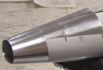
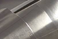
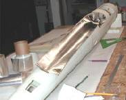
Beginning
with example B1. BVM's F-100 like the full size incorporates
molded in flush seam panels. Unlike smooth skin fuselages, molded
in panel lines do not require drawing lines on model surface. Butt
cut panels do not require an installation sequence. All panels and
hatch locations should be considered prior
to beginning. (Access hatch examples later).
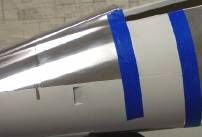
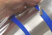
Example B2 shows 1 inch 3M Fine Line©
tape laid
along the outside perimeter of panel with a 1/64th to
1/32nd inch overlap "inside" the molded panel line.
While it appears to be “0” overlap the overlap is within
the molded panel line surrounding the “to be covered panel”.
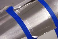
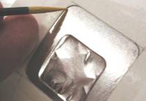
Example B3 shows ©
cut about 3/4 inch larger than
panel area to permit easy positioning & fast application.
After initial burnishing with index finger working from center to
edge of panel, use ©
fibrous burnishing
tool point to burnish against hard edge of taped along
panel perimeter. Trim excess and lift waste with the tape. Burnish
“across cut edge” with fibrous burnishing edge to smooth cut
edge. Note: Do not use “finishing pad” or sand
paper on ©
until all panels are applied to the
airframe.
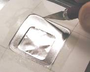
Burnish
To Hard Tape Edge |
Cut
then Remove Waste & Tape |
Burnish
Edge Down Smooth |
Flush Panel
Application on smooth surfaced fiberglass airframes:
Unlike
molded-in panel line fiberglass airframes, built up and glassed
wood airframes require the panel line pattern be drawn onto
the surface. This process is discussed on the first sheet
of our
instructions.
Example
#B9 |
Example
#B10 |
Example
#B11
|
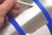
Example
#B9 George Maiorana burnishing new top panel to bottom panel
burnished to the airframe in normal fashion. The sharp edge of a
cuticle stick is perfect for a good hard edge against an adjacent
panel. The ideal method to create flush seam panels is to apply
an initial panel as if you are going to do an overlap. Then, after
lifting waste and tape, place tape along inside of that panel’s
perimeter forming a hard edge against which you burnish the next
panel.
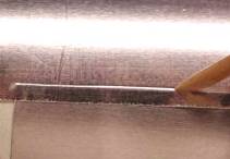
Example #B10 shows metal straight edge (available at local home
store) laid across intersect between new and installed panel. Many
straight edges are backed with thin cork to prevent slipping.
Lower edge
of straight edge is parallel to newly burnished edge between the
panels.
Dipping hobby knife in mineral spirits lubricates
edge increasing life of blade and smoothness of cut. Wipe the
fresh cut with alcohol to remove mineral spirit residue
immediately after making cut. When panel is cut, remove excess and
tape leaving a straight line between panels.
Lay cork backed
stainless ruler over panel line and draw a line on top of the
panel line using a black ink ball point pen. Drawing the pen
across the ©
gently will create the perfect
indentation between the two panels.
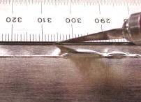
Example #B11 shows bottom of fuselage as the panel is being
applied. The
3M®
Scotch Bright finishing pad included with the AK packaged tools
will create a light dusting of aluminum when it is used. If you
use the finishing pad before the surface is completely covered,
aluminum dust will contaminate the uncovered aircraft surface
leaving particles under the aluminum.

Example #B12 |
Example #B13 |
Example #B14 |
Example
#B12 shows
faux access hatch template taped to surface of smooth fuselage side.
Square to adjacent panel lines for best appearance.
Example #B13 shows rounded point of cuticle stick drawn
around template perimeter. A ball point pen will accomplish this
same effect.
Example #B14 shows faux access hatch panel line being cut for
most authentic appearance.
|
© 2004
16115 Espinosa Drive
Houston, Texas 77083
281-530-8925 |
|